
Chiller Delta T Calculation: Temperature Difference, Flow and Cooling Capacity
A chiller’s kW rating does not tell the whole story. Supply temperature, return temperature and circulating water flow must be considered together. Delta T (ΔT) is the temperature difference that connects these operating conditions.
What is Delta T?
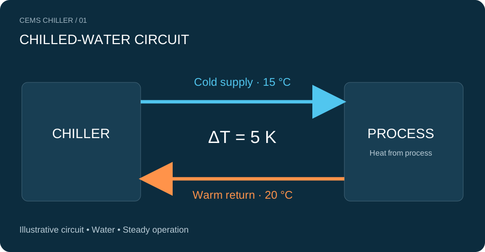
In a chilled-water circuit, ΔT is the difference between the warm return entering the chiller and the cold supply leaving it. Inlet and outlet are defined from the chiller’s perspective; the directions are reversed at the process machine.
With 15 °C supply and 20 °C return, ΔT = 20 − 15 = 5 K. A difference of 5 K equals a difference of 5 °C. This is not the difference between outdoor air and water temperature, the evaporator approach temperature, or the controller’s start/stop differential.
Calculating cooling load and flow
For a single-phase liquid under steady conditions, the sensible-heat balance is:
Q = (ρ × cp × V̇ × ΔT) / 3600
- Q: Thermal power / cooling load (kW)
- ṁ: Mass flow (kg/s)
- ρ: Liquid density (kg/m³)
- cp: Specific heat capacity (kJ/kg·K)
- V̇: Volumetric flow (m³/h)
- ΔT: Water temperature difference (K)
Using approximately ρ = 1000 kg/m³ and cp = 4.1868 kJ/kg·K for water gives this preliminary calculation:
V̇ ≈ Q / (1.163 × ΔT)
The 1.163 factor applies only to these units and the water approximation. Q calculated from measured flow and temperatures is heat transfer between the measurement points—not compressor electrical input or the catalogue capacity at every operating condition.
Example: 100 kW load at a 5 K difference
Assume a production line has a 100 kW thermal load. Water enters the process at 15 °C and returns at 20 °C:
- ΔT = 20 − 15 = 5 K
- V̇ = 100 / (1.163 × 5) = 17.2 m³/h
- In litres per minute: 17.2 × 1000 / 60 ≈ 287 L/min
This is a preliminary flow calculation. Selecting a pump also requires pressure losses through piping, filters, valves, the evaporator and process equipment. Verify that the selected chiller delivers 100 kW at the actual leaving-water and ambient temperatures.
What changes when Delta T changes?
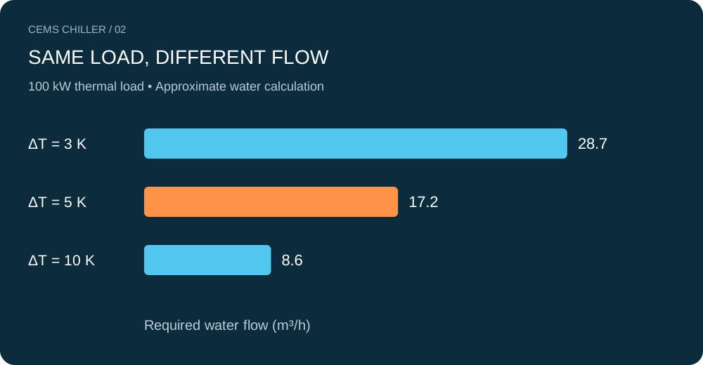
The comparison below keeps the load at 100 kW and uses water. A higher ΔT requires less calculated flow. This does not mean reducing an existing pump’s speed will safely deliver the same result in every installation.
| ΔT (K) | Thermal load (kW) | Water flow (m³/h) | Water flow (L/min) |
|---|---|---|---|
| 3 | 100 | 28.7 | 478 |
| 5 | 100 | 17.2 | 287 |
| 10 | 100 | 8.6 | 143 |
What is the correct design Delta T?
There is no universal ideal ΔT for every chiller or process. The 5 K value used here is an example, not a mandatory design condition. Injection moulding, printing, food processing and hydraulic equipment may require different supply temperatures, return temperatures and minimum flows.
Designing for a higher ΔT may reduce flow and pumping requirements where suitable. However, heat-exchanger performance, process temperature distribution and chiller limits also change. ΔT alone is not an efficiency or COP indicator. Evaluate compressor, pump and fan power together.
If measured Delta T is low or high
Low ΔT: Investigate reduced production load, excessive flow relative to load, bypass mixing, valve control or measurement errors. Low ΔT at part load is not proof of a fault.
High ΔT: This may be associated with higher process load or insufficient flow. Check filter condition, valve positions, trapped air, the pump operating point and measurement accuracy. A temperature difference alone cannot identify the cause.
Do not throttle flow simply to achieve a target ΔT. Maintain the manufacturer’s minimum and maximum flow limits and freeze protection. Pump and control changes should be evaluated by qualified technical personnel.
A checklist for reliable measurement
- Measure supply and return on the same circuit, accounting for mixing points.
- Record temperatures and flow simultaneously during stable production.
- Use compatible sensors with verified accuracy and suitable immersion and insulation.
- Record glycol type, concentration and average liquid temperature.
- Compare against design values at equivalent load and operating conditions.
Sensor difference error matters more at small ΔT: a combined 0.5 K error represents approximately 10% of a 5 K difference, but 25% of a 2 K difference. This example covers temperature-difference error only; flow-measurement error is additional.
Can the same factor be used with glycol?
Not directly. Glycol type, concentration and temperature change density and specific heat. Use the fluid supplier’s ρ and cp data for the final calculation. Account for viscosity changes when calculating pressure losses and selecting the pump. The tool below provides approximate calculations for water only.
Water-flow calculator
Preliminary calculation • Pure water • 5–30 °C • Not a substitute for equipment or pump selection.
Frequently asked questions
Does zero Delta T mean no cooling?
If the measurements are correct and flow exists, no temperature difference means zero net sensible heat transfer between those points in this calculation. Sensor resolution, bypass flow and transient conditions must be checked before declaring a chiller fault.
Will halving flow double Delta T?
Mathematically, only if the transferred thermal power remains constant. In practice, changing flow may alter process and heat-exchanger performance; stay within manufacturer limits.
Can Delta T alone determine capacity?
No. Flow and fluid properties are also required. Correct selection combines load, supply and return temperatures, fluid properties and ambient conditions.