
Primary–Secondary Process Cooling Loops and Heat Exchanger Selection
Sending chilled water directly to a machine is not the best arrangement for every plant. Different water quality, pressure, glycol concentration or operating requirements may justify separating the chiller side from the process side. The decision depends on fluids and operating conditions, not cooling capacity alone.
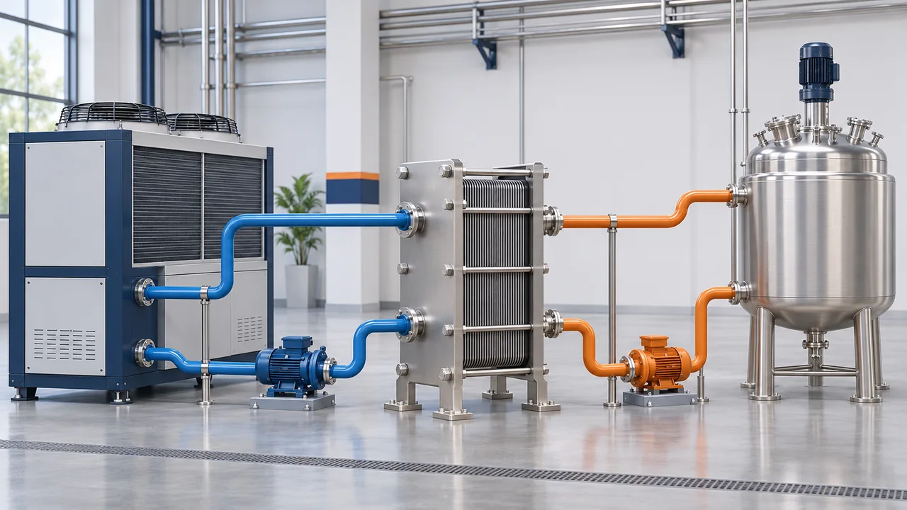
What are the primary and secondary loops?
In this article, the primary loop is the water or water–glycol circuit between the chiller and an intermediate heat exchanger. The secondary loop circulates fluid between that exchanger and the process equipment. The primary loop is not the chiller refrigerant circuit. The secondary fluid is not necessarily the product itself: it may be reactor jacket water or machine cooling water.
The process transfers heat to the secondary fluid. The exchanger passes this heat to the primary fluid, and the chiller evaporator transfers it to the refrigerant. The condenser rejects heat, including the compressor contribution, to ambient air or a condenser-water system. An intermediate exchanger does not generate cooling.
Does every primary–secondary system need an exchanger?
No. With a common fluid, a low-resistance common pipe or suitable hydraulic separator can reduce interaction between pumps. It does not physically separate the fluids: water can mix in the common volume. An exchanger keeps the two streams in separate passages during normal operation. [1, 2]
If independent flow is the only requirement, an exchanger may introduce an unnecessary temperature approach and pumping duty. Where fluid quality, chemical compatibility or pressure separation matters, evaluate an exchanger arrangement. Terminology varies between projects, so identify equipment and flow directions explicitly on drawings.
When is separation useful?
- Water quality: Process water returning from an open tank with particles or sediment can be kept out of the chiller evaporator. Fouling remains a concern on the process side of the exchanger.
- Different fluids: One circuit may contain glycol while the other uses treated water. Concentrations and materials are selected separately.
- Different pressures: A high-rise distribution system or pressurised machine circuit may be separated from the chiller using a suitably pressure-rated exchanger.
- Different operation: Flow and temperature control for machine groups can be arranged independently, with clearer maintenance boundaries.
An exchanger alone does not guarantee hygiene or zero leakage. An internal leak may transfer fluid from the higher-pressure side and overpressure the lower-pressure circuit. For critical duties, assess double-wall construction, leak detection or an intermediate loop through a project-specific risk review.
Plate or shell-and-tube: choosing the construction
Plate exchangers are not a single interchangeable product type. Gaskets, brazing, welding, channel width and service access affect suitability. [3, 4]
| Type | Typical strength | Selection checks |
|---|---|---|
| Gasketed plate-and-frame | Compact water-to-water duty; plate pack can be opened for service | Plate/gasket compatibility, fouling, pressure rating and service space |
| Brazed plate | Compact solution for suitable clean closed loops | Braze material and narrow channels; plate pack cannot be dismantled for mechanical cleaning |
| Welded or semi-welded plate | Processes requiring a specialised construction | Which sides contain gaskets, cleaning method and model limits |
| Shell-and-tube | Construction can be tailored to pressure, temperature and maintenance needs | Tube/shell-side allocation, velocities, footprint; cleaning access depends on construction |
| Wide-gap plate, spiral or special design | Particle-bearing, fibrous or viscous media | Particle size, blockage risk, cleanability and supplier verification |
No type is automatically suitable for every dirty or chemical fluid. “Stainless steel” is not a sufficient material specification: chloride content, pH, temperature and cleaning chemicals must be considered together.
Approach temperature: why is process water warmer?
A finite exchanger requires a temperature difference to transfer heat. If the process needs 10 °C supply water, primary water entering the exchanger at exactly 10 °C cannot deliver that duty at the design load. A colder primary supply is selected; the required approach follows from the thermal selection.
In a counter-current example, primary water warms from 7 to 12 °C while secondary return water cools from 15 to 10 °C. The terminal differences are 10 − 7 = 3 K and 15 − 12 = 3 K. These are illustrative values, not a universal “3-degree loss” rule.
A closer approach generally calls for more heat transfer area. Lower chiller leaving-water temperature may affect chiller capacity and power consumption. Evaluate exchanger cost, chiller operating point and pumping energy together. [3]
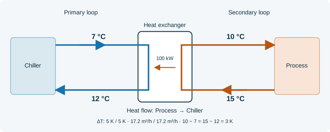
A 100 kW flow example: must both flows match?
At steady state, neglecting heat exchange with the surroundings, the heat duties on the two sides are approximately equal:
For water: Q (kW) ≈ 1.163 × V̇ (m³/h) × ΔT (K)
With water and a 5 K loop temperature difference on each side, the approximate flow in each loop is:
If the primary loop is designed for a 3 K ΔT, its flow becomes approximately 28.7 m³/h at the same duty. The secondary flow remains 17.2 m³/h if its ΔT stays at 5 K. Recheck the exchanger using the revised four temperatures. Equal duty does not imply equal flow.
The 1.163 factor is an approximation for liquid water. Glycol, oil and other fluids require density, specific heat, viscosity and thermal conductivity at the actual operating temperature. Recalculate pump selection too. Heat imparted to the fluid by pumps and other auxiliary loads must be included separately in the system duty.
Pumps, controls and protection
- Size each pump for the pressure losses of its own piping, exchanger, filters, valves and equipment. Building height is not the same as circulation pump head in a closed loop; fill pressure and open-tank arrangements require separate assessment.
- Maintain the evaporator minimum/maximum flow and permitted rate of flow change. Closing a secondary valve must not compromise chiller flow.
- Provide expansion accommodation, pressure protection, venting, filling and draining for each independent closed loop. Select buffer volume from load variation and minimum run-time requirements.
- Provide temperature sensing at all four exchanger connections and suitable pressure/Δp measurement points. Monitor dirty filters and loss of flow.
- Coordinate the process-supply control valve or pump with chiller controls. Prove flow before enabling cooling; apply freeze protection and pump interlocks according to the equipment requirements.
Cold surfaces require condensation control with continuous vapour-resistant insulation. Adding an exchanger does not, by itself, guarantee minimum flow or freeze protection.
What should be monitored in operation?
At commissioning, record the clean exchanger's four temperatures, two flow rates and pressure drop on each side. Compare later readings at similar load and temperature conditions. Rising pressure drop or a larger approach may indicate fouling, but also investigate inadequate flow, trapped air and control issues. [5]
Filtration, dirt separation and water treatment perform different tasks. Base cleaning intervals on operating evidence. Confirm cleaning-agent compatibility with metals and gaskets, and shut down, depressurise and isolate equipment safely before maintenance.
Information needed for design and quotation
- Normal and peak cooling duty; batch duration and load profile where applicable.
- Fluid identity, glycol concentration, contamination and compatibility information for both sides.
- All four inlet/outlet temperatures, required flows and allowable pressure drops.
- Operating/design pressures, ambient temperature, chiller operating point and freeze risk.
- Cleaning method, service clearance, redundancy, control tolerance and future capacity needs.
Start with process requirements, then establish why separation is needed and define the exchanger duty. Finally verify the chiller, pumps, buffer and controls as one system. A single catalogue kW figure is not a complete selection.
Frequently asked questions
Does a hydraulic separator isolate clean and dirty water?
No. A separator with a shared water volume is not a physical fluid barrier. Separate fluids require a suitable exchanger or another isolation arrangement.
Will an exchanger increase chiller capacity?
It does not create cooling capacity. It transfers heat; the required approach and additional pumping loads belong in the system selection.
Can I use the water flow equation unchanged for glycol?
No. Recalculate thermal and hydraulic performance using mixture properties at the actual temperature and concentration.
Is a plate exchanger always the best choice?
No. Fluid properties, particle size, pressure, temperature, maintenance and safety requirements determine the appropriate construction.