
Jacketed Tank Cooling Systems: How to Select a Chiller
Tank volume alone does not determine chiller capacity. The required cooling time, product temperature and heat transfer through the jacket all matter. A useful selection starts with a repeatable batch temperature profile rather than a nominal tank-to-kilowatt rule.
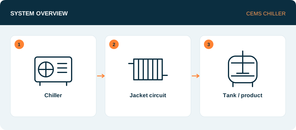
How jacket cooling works
Chilled water or a suitable heat-transfer fluid circulates through the tank jacket. Heat passes from the product through the vessel wall to this fluid and is then rejected by the chiller. The product and utility fluid remain separate in normal operation. Jacket geometry, effective area and mixing conditions limit heat transfer. [1] [2]
Include cooling time in the duty calculation
For a batch without reaction heat or phase change, a starting calculation is Q = m × cₚ × (Tinitial − Ttarget) / t. With mass in kg, specific heat in kJ/kg·K and time in seconds, Q is in kW. This is the average product load. Vessel thermal mass, agitator heat, ambient gains and simultaneous users require separate consideration.
Worked example: a 1,000 kg batch
Assume 1,000 kg of product with a specific heat of 4 kJ/kg·K must cool from 40 °C to 20 °C in one hour. The average product duty is 1,000 × 4 × 20 / 3,600 ≈ 22.2 kW. This is an illustrative calculation, not a recommendation to order a 22.2 kW chiller. As the product approaches its target temperature, the driving temperature difference decreases; check the cooling time against the available heat-transfer area.
Can a larger chiller compensate for a small jacket?
Not necessarily. Limited jacket area, fouling or poor mixing of a viscous product may restrict cooling even when chiller capacity is adequate. Product, jacket supply and jacket return sensors serve different purposes. Select pump flow and pressure from vessel data and do not exceed the jacket pressure limit. [1] [2]
Control and commissioning
Controlling product temperature is different from maintaining a constant chiller outlet temperature. A control valve, variable-flow arrangement or separate temperature-control loop may be appropriate. Keep heating-to-cooling transitions within vessel and material limits. Record cooling curves at both full and partial fill during commissioning to verify the specified batch time. [3]
Information needed for chiller selection
- Minimum and maximum batch mass, density and specific heat
- Initial and target temperatures and allowed cooling time
- Product viscosity, agitation and jacket area
- Permitted jacket flow, pressure and connections
- Batch schedule, ambient conditions and concurrent loads
Frequently asked questions
Can every tank use the same chilled-water temperature?
No. Check product freezing, crystallisation and wall deposition risks as well as vessel limits. Colder water is not automatically the better process choice.
Is a buffer tank always required?
No. Evaluate minimum circuit volume, low-load operation and transitions between batches.